|
Introduction
All of our tools with simulation (WIZ-C Professional, AVIDICY, C Compiler, and WIZASM) now
include External Device Simulation
What is external device simulation ?
External device simulation allows the user to add and connect typical devices which might be
connected to the AVR or PIC MCU in real world examples considerably enhancing the debugging capability of these tools. External device pins may be connected to the MCU, to a low or high logic
level, or left unconnected.
For example consider a 7 segment display, or an LCD module. Previously with our tools (or with
other simulators), the program would be simulated, and the ports traced. To debug these devices
would require that text trace files, or the waveform analyser be used and examined to convert
patterns into displayed values manually. In practice this is so hard, that only when the real circuit
was constructed would it be possible to check out correct operation.
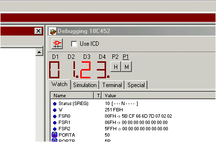
Here is a screen shot showing a multiplexed 7 segment display with 2 pushbuttons connected to a
WIZ-C application, note that the display shows the lit digit in bright red, but the unlit digits are
shown in a dull colour, this simulates persistence of vision with multiplexed displays. Also shown are two push buttons.

The device types include :
Logic Analyser, Clock Generator, LED’s, Seven Segment Displays, Serial Terminals, I2C Terminal (to simulate I2C devices), Device pin outs, Hex Keypad, Bitmap images, Shapes, Analogue potentiometer, PWM voltmeter, Push Buttons and LCD modules, I2C terminal, Serial EEPROMs.
|

